The most important component to understand in electronics is the resistor. This is because we use the resistor to model much more complex systems.
If you understand how to do "resistor math" then solving complex systems becomes much easier.
Let's review the basics.
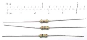
- They come in various values that are expressed in Ohms.
- You can determine their value by using either a multimeter or by reading the colored bands on them.
- A resistor is used to resist current flow.
We need to introduce a new symbol because it is used extensively in electronics.
The symbol for an ohm is é.
Whenever you see é written down, you can say "ohm" or "ohms" if plural.
Here is the schematic symbol for a resistor, and some real life examples.
Schematic Symbol

Actual Image
Expected Values of Resistors
Resistors come in many values from 1 Ohm to 10 million Ohms. Since it is very inconvenient to write 10,000,000 out, it is common to express the values of resistors in Engineering Notation. While engineering notation is a broad concept, you really only need to know 2 terms when dealing with resistors.
| Name | Multiply By |
| Kilo | 1,000 |
| Mega | 1,000,000 |
Kilo and Mega are the Greek prefixs that mean 1,000 and 1,000,000 respectively. So if I told you that a resistor was 5k, then you know that I really mean this.
5k = 5 x 1000 = 5,000 ohms or 5,000é (pronounced 5 kiloohms)
Likewise, 5M is the same as this.
5M = 5 x 1,000,000 = 5,000,000 ohms or 5,000,000é (pronounce 5 megaohms)
Some common resistor values are listed in the table below. You should be familiar with these values because you will see them a lot in electronics.
| Name | Value |
| 100 | 100é |
| 1k | 1,000é |
| 2.2k | 2,200é |
| 4.7k | 4,700é |
| 100k | 100,000é |
| 1M | 1,000,000é |
Determining the Value of a Resistor
There are 2 common ways to determine the value of a resistor, and we will cover them both.
- Reading the color bands
- Using an ohmmeter
Reading the Color Bands
Most hobby resistors have color bands on them that help you to determine their resistance value. Reading the bands is like solving a puzzle. Some people enjoy it, some people hate it. You'll have to give it a try and see where you stand. Don't worry if you hate it, there are always other ways to figure out what resistance a particular component is.
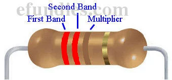
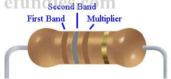
Let's look at a close up of a resistor's color bands.
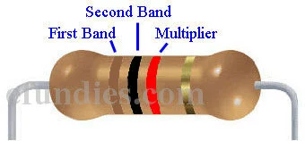
Ignore the gold band for now. The meaning of a color depends on if it is in the first two bands, or if it is the third band. The first two bands are used as regular numbers, while the third band is used as a multiplier. Let's take a look at a table of what the colors mean.
| Color | 1st band | 2nd band | 3rd band (multiplier) |
|---|---|---|---|
| Black | 0 | 0 | x1 |
| Brown | 1 | 1 | x10 |
| Red | 2 | 2 | x100 |
| Orange | 3 | 3 | x1,000 |
| Yellow | 4 | 4 | x10,000 |
| Green | 5 | 5 | x100,000 |
| Blue | 6 | 6 | x1,000,000 |
| Violet | 7 | 7 | x10,000,000 |
| Gray | 8 | 8 | x100,000,000 |
| White | 9 | 9 | x1,000,000,000 |
Focus on the top 5 rows, they are the most important. For now, you can ignore green, blue, violet, gray and white. After you get the hang of resistor color codes come back and review the second half of the table.
Examples of Resistor Values
Let's see some examples to understand how the table works.
Example 1
| Band 1 | Band 2 | Multiplier | Value |
| Brown | Black | Red | ??? |
Example 1: Brown - Black - Red
Referring to the table, brown in band 1 = 1, and black in band 2 = 0. So far our value is 10. Finally, red in band 3 = x 100. So our final value is:
10 x 100 = 1,000 = 1k ohms or 1ké
Example 2
| Band 1 | Band 2 | Multiplier | Value |
| Red | Red | Brown | ??? |
Example 2: Red - Red - Brown
Referring to the table, red in band 1 = 2, and red in band 2 = 2. So far our value is 22. Finally, brown in band 3 = x 10. So our final value is:
22 x 10 = 220 = 220 ohms or 220é
Example 3
| Band 1 | Band 2 | Multiplier | Value |
| Orange | Orange | Orange | ??? |
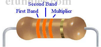
Example 3: Orange - Orange - Orange
Referring to the table, orange in band 1 = 3, and orange in band 2 = 3. So far our value is 33. Finally, orange in band 3 = x 1000. So our final value is:
33 x 1000 = 33,000 = 33k ohms or 33ké
Common Resistor Values
It seems that some resistor values show up more often than others. It is very handy to be able to recognize these most common values without having to look them up. Here we will present you with a table of the common values. Notice that we have used some higher numbers here. Refer to this table if you need help figuring out a resistors value.
| Band 1 | Band 2 | Multiplier | Value |
| Brown | Black | Brown | 100 ohms |
| Red | Red | Brown | 220 ohms |
| Yellow | Violet | Brown | 470 ohms |
| Brown | Black | Red | 1k ohms |
| Brown | Red | Red | 1.2k ohms |
| Red | Red | Red | 2.2k ohms |
| Yellow | Violet | Red | 4.7k ohms |
| Brown | Black | Orange | 10k ohms |
| Yellow | Violet | Orange | 47k ohms |
| Brown | Black | Yellow | 100k ohms |
| Brown | Black | Green | 1M ohms |
Using an Ohmmeter to Measure Resistors
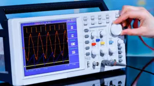
The multimeter is probably the most used piece of equipment on an electronics bench. Multi implies that the meter has multiple functions. Most multimeters can perform the following functions.
- Measure voltage - Voltmeter
- Measure current - Ammeter (because current is measured in amps)
- Measure resistance - Ohmmeter (because resistance is measured in ohms)
In this guide we are going to use our multimeters in ohmmeter mode, or simply "in ohms".
Example Ohmmeters
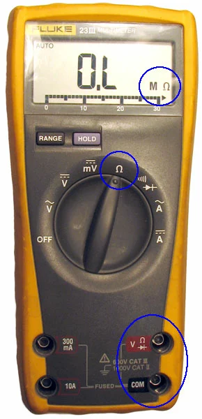
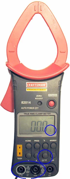
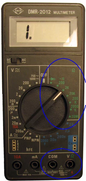
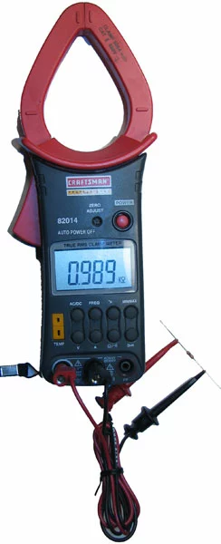
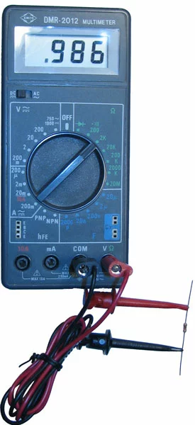
Here we will show you 3 different multimeters and how to put them in ohmmeter mode.
| Fluke | Craftsman | EmCo |
|
|
|
|
|
|
As you can see, all 3 of these meters have different procedures for putting them in ohmmeter mode. You will have to figure out how your meter works based on these examples. The important things to note are:
- Know where to set your dial
- Figure out which plugs to connect your wires to
- Understand what the display is showing
How to Hold The Resistor
The correct way to connect a resistor to an ohmmeter is with spring-loaded clips, like this.
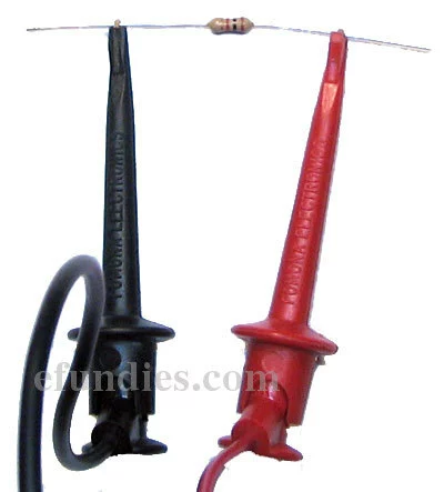
This is correct.
Now we will show the incorrect way to hold a resistor. Do not do this!
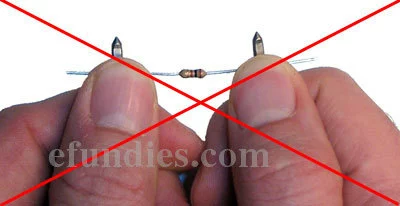
This is incorrect!
By using your fingers to hold the resistor to the probes you have changed the resistance that you are measuring. You will not get accurate results if you do this. If you do not have spring clips, then set the resistor down on something like a piece of paper or a plastic cutting board and press the probes into it without touching them.
Hooking Up the Meters
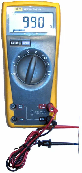
Once you get your meter set up correctly, you can clip on to the resistor and get an accurate reading of its value. Here are the above 3 meters measuring the same resistor.
| Fluke | Craftsman | Em-Co |
|
|
|
|
|
|
As you can see, all 3 meters are reading a different value. You can not quite make out the bands of the resistor in the picture, but they are:
| Band 1 | Band 2 | Multiplier | Value |
| Brown | Black | Red | 1k ohm |
Brown - Black - Red
This seems reasonable. All meters are reading pretty darn close to 1k ohm. When using a meter to measure a resistor you will have to get used to values being close, but not quite exact. All meters are calibrated slightly differently and will read slightly different from each other.
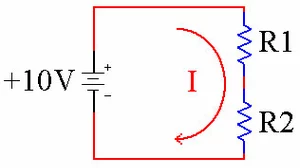
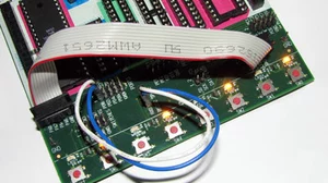
Using a Resistor to Limit Current
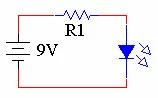
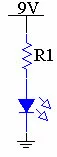
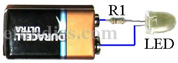
One of the most common uses of a resistor is to limit current flowing into a device. We will use LEDs as an example.
LEDs are rated in how many amps of current you can allow through them before they burn out. By themselves LEDs have virtually no resistance so they will allow huge amounts of current through. However, they will burn up almost immediately if connected to a battery without a current limiting resistor. It is up to you, the system designer, to put the correct resistor inline with the LED to limit the amount of current that the LED receives, because the LED manufacturer has no idea what voltage of battery you are going to use in your project. Let's look at an example using a resistor and an LED.
| Schematic 1 | Schematic 2 | Actual Image |
|
|
|
Above we have shown two different schematics and one real life circuit. Notice that all 3 are electrically identical. This is an example of using a resistor to limit current. In this configuration we call the resistor a current limiting resistor.
Using Ohms Law to Calculate Which Resistor to Use
The real question here is what value of resistor do we need to install to properly limit the amount of current getting to the LED. When we bought the LED, the data that came with it told us that this LED can handle 0.050 amps of current (or 50 milliamps). Using Ohms Law, we know that V = 9 volts and I = 0.050 amps. We can use one of the forms of Ohms Law to calculate R.
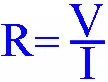
Ohms Law, R = V / I
Plugging in the values that we know, we get.

R = 9 / 0.050 = 180 Ohms
So R = 9 / 0.050 or 180 Ohms. If we could find a 180 Ohm resistor and put in inline with our LED, then 0.050 amps would flow through the LED and we would not burn up the LED. A 180 ohm resistor is:
| Band 1 | Band 2 | Multiplier | Value |
| Brown | Gray | Brown | 180 ohms |
Brown - Gray - Brown
Conclusion
Hopefully now you have a better idea of what resistors are and how you can use them in electronics. In this guide you learned how to:
- Use the resistor color code to look up resistors
- Use an ohmmeter to measure their value
- Use an appropriate resistor to limit the current flow through devices.