MIDI Controlled Solenoids with Arduino and Ableton Live - Part 1

Thumbnail image of Jason Bauer
Jason Bauer
November 26, 2019 (Last Updated: ) | Reading Time: 9 minutes

In this 3 part article we teach you how to control electronic solenoids from Ableton Live, by using some Arduino programming, a little bit of MIDI knowledge, and some basic electronics.

At the end of the series you will have a setup that is capable doing this.

This is a pretty complex topic so it is split into 3 parts to make it easier to follow. The 3 parts cover:

Feel free to jump around to all of the parts to get a feel for what is going on.

Part 1 - Arduino and Hardware

In this article we cover the hardware requirements for playing solenoids from Ableton Live. In order to play MIDI notes on solenoids you need the following hardware:
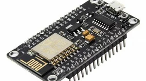
Each part of this list is very flexible and you can use whatever parts you have on hand.

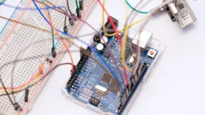
Arduino with Native USB

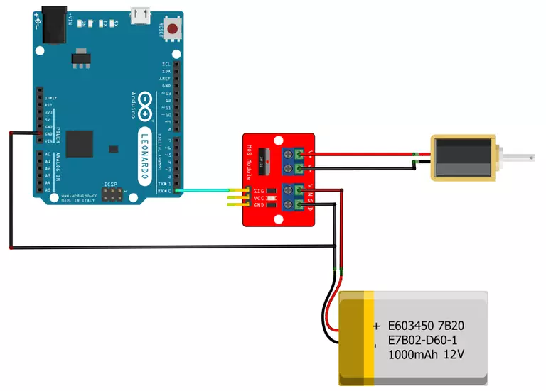
You need to use an Arduino that has native USB support. This project uses the MIDIUSB Library which relies on an Arduino device with native USB functionality. This means that you need a device such as a Leonardo, Micro, Due, or Zero. We used an Arduino Leonardo clone from Borderless Electronics, but you can also use a genuine Arduino like this one. The Arduino is the connection between Ableton Live and the output transistors.

You can see that the MIDI data generated in Ableton Live flows into the USB port of an Arduino, where it is used to control solenoids.

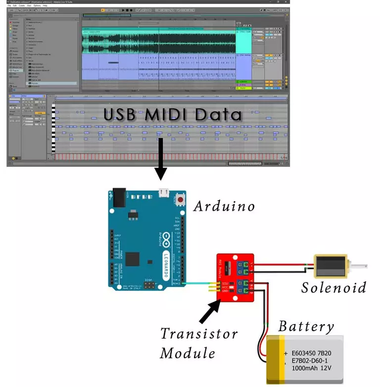
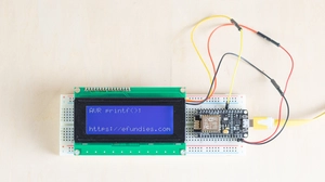
The MIDI data is generated by Ableton Live and is sent out the USB port to an Arduino using the External Instrument MIDI device built in to Ableton Live. The Arduino software interprets the MIDI stream and uses it to turn output pins on and off.

The output pins are connected to transistor modules that connect the solenoid to the battery, causing the center plunger in the solenoid to move.

The software that we used for this demo is open source and shared in the next article.

Solenoids

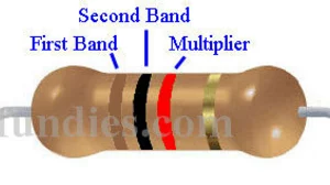
You can theoretically use anything for the output sound here. Motors, relays, and buzzers will all work as long as your transistors can drive them and you provide enough power. We chose to use solenoids. You can get the solenoids on Ebay for very cheap. A typical solenoid looks like this:

A typical solenoid
A typical solenoid

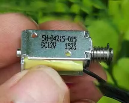
The ones we used have a 4mm stroke, require 12 Volts and 120 milliamps, and have a spring return.

The spring return is important. Be sure that you buy a solenoid with spring return. This is what brings the plunger back to neutral when you turn the pin off and remove power to the solenoid.

You can most likely use 5 volt solenoids as well, just be sure to use a matching power supply.

These solenoids have black and red wires, but it doesn't matter which way you hook them up.

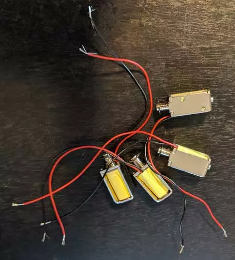
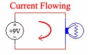
Solenoids have 2 wires, frequently a black wire and a red wire, but in reality the color of the wires is not important. When you apply power to the wires an electromagnet is created and the center plunger moves forward. Then when you remove power the electromagnetic field collapses and the center plunger is free to return to neutral.

It does not matter which way you hook the solenoid wires up, but if they have black and red wires then it is common to connect the black wire to ground (GND) and the red wire to plus (+).

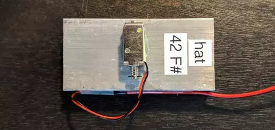
Mount and Wire the Solenoids

It's nice to have the solenoids mounted to something with a bit of mass so that you can set them next to what they are going to hit and make noise. Many times the come with metric tapped holes that you can use to mount them. We chose to use E6000 glue and simply glued the solenoids down to some scrap aluminum flat bar. Be sure to align the solenoid so that the plunger pushes past the edge of the flat bar when it is in the forward position.

We just glued our solenoids down to aluminum flat bar drops.

Extend the wires of the solenoids to 3 or 4 feet with any flexible wire. We used 24 AWG zip cord from Amazon.

This 24 gauge zip cord is perfect for wiring solenoids because it is very flexible.

Solder the solenoid wires to the zip cord and insulate it with some heat shrink tubing if you have it. Attach the wires to the mass as a strain relief because these little solenoids are going to be moved around a lot.
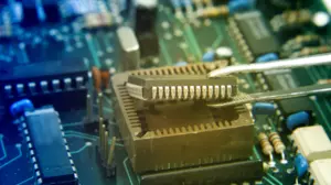
Output Transistors

In order for the Arduino to turn something on and off like a solenoid (or a motor, buzzer, or other device) there needs to be an output driver between the Arduino and the device that is being turned on. The simplest output driver is a transistor. An easy way to get a transistor is to buy one that is already mounted on a board with screw terminals, all ready to go. For this project we used these.

These modules are available on Amazon and Ebay and they are very inexpensive.

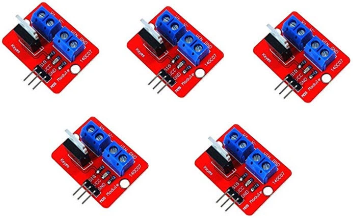
They have an IRF520 MOSFET on them which is perfect for controlling from an Arduino pin. They are capable of driving up to 5 amps each, which is about 40 times as much as we need (our solenoids only require 120 milliamps, or 0.120 amps). With the screw terminals they are simple to wire up in a project like this.

The wiring is simple, partly because these transistor modules have a common ground, meaning your power ground and your Arduino ground are connected to each other.

The GND wires are connected together on the IRF520 modules creating a common ground.

Connect your Arduino output pin to the transistor modules SIG pin, which stands for signal input. When the Arduino pin is high the transistor will turn on, the solenoid will fire, and the plunger in the solenoid will move forward. The VCC pin on these modules is not connected to anything and can be ignored. It is only there to make the connector compatible with other output devices.

You can see that the **VCC** pin is not connected to anything on these modules.

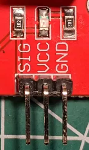
When the Arduino pin is low the transistor will turn off disconnecting the power supply from the solenoid and the spring return in the solenoid will return the plunger back to its normal resting place.

Note that we don't need an h-bridge in this circuit because the spring on the solenoid returns the plunger back when we remove power. An h-bridge would be needed if we wanted to do something like spin a motor both forward and backward. In this case the spring is our reverse.

Power Supply

The last thing that you need for this project is some sort of power supply to move the solenoids. The output from the Arduino is not strong enough so we are running it through a transistor. The transistor will turn some sort of power on and off, but we need to provide that power.

It can be simple, such as a 9 volt battery or a few AA cells in series to get at least 6 volts. You can use an RC battery or a recycled wall wart. If you use the IRF520 transistors that we used above then a 12 volt supply will work perfectly.

In this drawing we are using a lipo battery to drive the solenoid through an IRF520 module.

The power supply is connected to the VIN and GND pins of the transistor modules. If you have more than 1 module then you have to connect them all together, in parallel.

When you have more than one IRF520 output module you need to connect their power together in parallel.

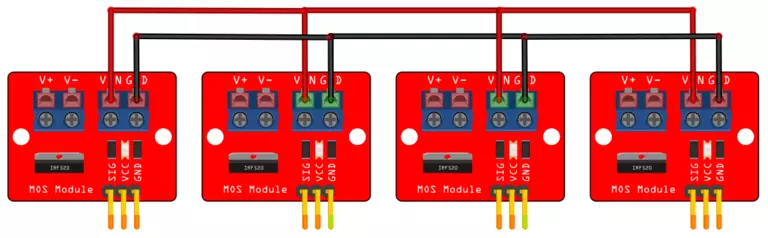
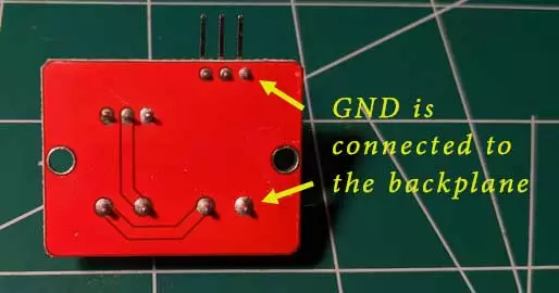
On these modules the two grounds, both labeled GND, are connected together on the back plane. This means that there is no reason to run a second ground wire from the Arduino to the 3 pin header; the high current ground connection on the 2 pin screw terminal is sufficient, as long as at least one ground wire runs from your power supply back to your Arduino.

Here’s a closeup of how we wired our IRF520 modules. You can see that the power to the modules is in parallel.

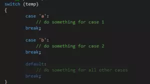
In addition these modules do not use the VCC pin so you can ignore it on all of them. Each module needs to connect to a dedicated output pin on the Arduino. We used pins 0 through 5, but you can use whatever pins you like. You will have to modify the pin assignments near the top of the source code file in the next article. It looks like this:

// these are the arduino pins that the solenoids are hooked up to
enum drumPins {kickPin = 0, snarePin = 1, hhPin = 2, crashPin = 3, cowbellPin = 4 , openhatPin = 5};

  If you use a different arduino you might have different pin mappings.

Powering the Arduino

A note about providing power to the Arduino. The Arduino can get power from either the USB port when it is connected to your PC or from the on-board power regulator.

Since this project is connected to your PC when in use we do not have to provide any sort of other power for the Arduino. However, since we have 12 volts available you can connect the pin labeled VIN on a Leonardo to your 12 volt rail without any problems. The Arduino Leonardo is fully capable of dual source power, and 12 volts is not too much for the on board regulator. This feature is taken advantage of on some other projects on this site.

In this project simply power the Arduino over USB while powering the output solenoids with a separate 12 volt source (unless you buy 5 volt solenoids, then use a 5 volt source for them). Be sure to connect your Arduino's ground and your power supply's ground together so that the output transistors actually turn on.

Debugging without a Power Supply

You can debug your code without the power supply turned on without issue. The output modules that we used here will still light up to let you know that they are getting an on signal from the Arduino, but it will not be as bright as when the external power supply is connected. Since there is no power connected, the solenoids will not move. Then once you have your code working properly you can connect the external power supply and the solenoids should start moving. Remember that the external power supply is independent of the USB power that the Arduino is running on.

This is a piece of plywood with 6 IRF520 modules mounted on it, an Arduino, a button board, and a power supply. You can see that the Arduino GND and the power supply GND are connected together.

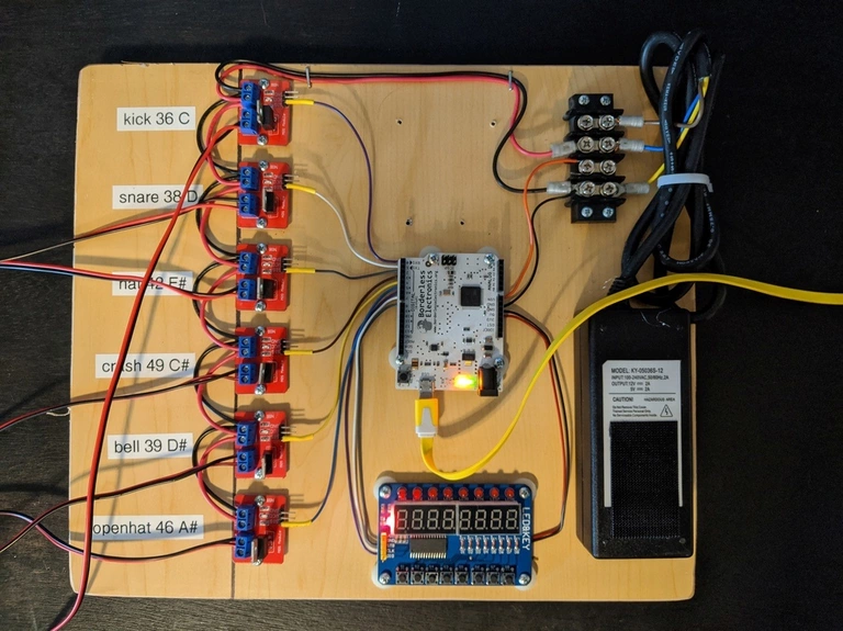
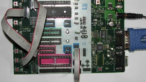
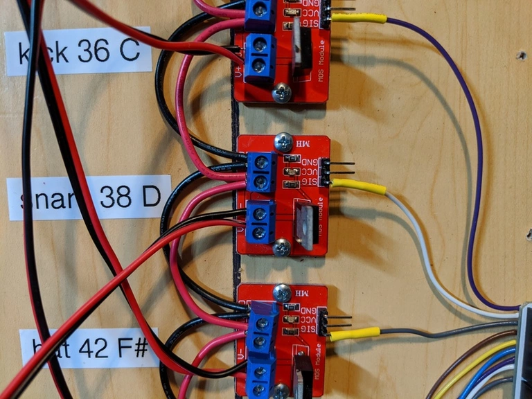
That should be all the hardware that you need to make an Ableton Live powered Arduino solenoid project. We mounted it all together on a piece of plywood so that it would survive a few months of experimentation.

Source Code

The next article covers the Arduino source code and MIDI theory needed to make this project work. MIDI Controlled Solenoids with Arduino and Ableton Live - Software and MIDI If you have any questions please feel free to ask them in the comment section below.

Comments

avatar

Deividas - 2020-03-10 20:10:19

reply

Hello, thank you for such an amazing and detailed tutorial.

I am a multimedia designer and would love to make an arduino/solenoid project for my steel tongue drums that I make.

Could you tell me if this setup allows me to achieve very fast speed with solenoids? Also is it posible to somehow control the velocity of solenoid?

avatar

Jason Bauer - 2020-03-14 22:31:58

Yes, you can get very fast speeds.

If you want to control the velocity of the solenoid, then all you have to do is in the function called "handleNoteOn" change the "digitalWrite" to "analogWrite" and pass the midi velocity in. It will take some fine tuning. I found that my solenoids wouldn't budge with a velocity of less than 50.

avatar

Jan - 2020-04-25 10:46:27

reply

Hey, nice project. This motivates me to start an own project. Can you tell me how many soneloids i can attach to the arduino and how many solenoids i can run with abelton. I already made a first try with servos yesterday, therefore i tried use the servo driver board, i didn't work. With kind regarss Jan

avatar

Jason Bauer - 2020-04-25 15:09:35

You can hook up as many solenoids as you want. Each arduino leonardo has 13 I/O pins and you can use all of them. After that you can add more arduinos and bind them as MIDI output devices in Ableton. At some point in time you may need more watts out of your power brick.

avatar

daerim - 2020-04-28 12:49:16

reply

Hey, I am really thankful for the project. And I just wanna know about the Arduino board. Can I also use Arduino Uno instead of Leonardo??

avatar

Jason Bauer - 2020-09-01 20:33:10

Yes, absolutely!

avatar

Dan Jeans - 2020-04-29 11:20:11

reply

Hi,

Thank you for this amazing project. I can't wait to get started. There doesn't seems to be much mention of the button board in the instructions though. I have bought one but I'm unsure of it's function and wiring etc. Can you please advise?

Thanks

avatar

Jason Bauer - 2020-09-01 20:35:31

The button board is not necessary at all for this project, but it sure does make it cooler!

The board is a cheap TM1638 clone from ebay, and I use the TM1638lite library to control it.

avatar

Ian Taylor - 2020-08-29 20:38:25

reply

Aloha Jason, thanks for posting this! I really appreciate it. I followed what you did, bought a Leonardo board and the same mosfet cards, an Adafruit 12V large solenoid and wired it up, loaded your code into it and worked!

I am trying to use MIDI velocity. I think I get what you mean about changing digitalWrite to analogWrite, I was able to do that in the lines of code two lines below "case kickMidiAlt:"

I didn't understand "be sure to double to value because midi is 0-127". I'm not sure how to double the value as MIDI only goes up to 127 so how do I double a velocity of 100? Where do I do that? I'm probably getting it all wrong but any clarification of what else I need to do use velocity would be great.

Thanks again for posting the article, it was a big help!

avatar

Jason Bauer - 2020-09-01 20:37:43

In handleNoteOn you get a velocity that came from rx.byte3. That value will be between 0 and 127. If you multiply it by 2 before sending it on to analogWrite it would scale better.

avatar

milan - 2020-09-30 14:33:42

reply

hello, what amperage should I choose for the 12V power supply?

avatar

Jason Bauer - 2020-10-02 15:35:08

I bet 1 amp would be plenty, and 2 amps is definitely enough.

avatar

Marius - 2021-08-15 20:49:09

reply

hallo jason, do you know if it´s possible to add MIDI IN to the arduino to control the solenoids direct with a external Midi Sequencer? thank you very much for this post, i´ll can´t wait for the parts to arrive:)

avatar

Jason Bauer - 2021-08-16 00:02:37

If the external sequencer has standard MIDI output, then it's pretty easy. You can feed the MIDI stream in on a pin and there are plenty of examples online about how to parse the serial stream.

If it's a USB device, like an Akai, then you'd have to get a USB host adapter, come up with a driver solution, and really dig into the USB packet structure. Probably doable, but probably very hard.

The middle-of-the-road solution might be a raspberry pi with the USB MIDI keyboard on one port and the Arduino on another, and some MIDI sequencer doing what Ableton is doing in my project.

avatar

Frank - 2023-02-28 02:36:13

reply

This may be a silly question, but can you trigger LED's with this set up as well? I was hoping to trigger an LED and solenoid at the same time..

Thanks

avatar

Jason Bauer - 2023-02-28 08:36:00

Yes, absolutely. Just connect the LED to the same pin as the solenoid.

Since this is set up to have the plunger move forward when the Arduino pin is high, you'll want to connect the anode, or (+) pin of the LED, to the Arduino pin. Use a small current limiting resistor, such as 100 ohms, and connect the cathode (-) to ground.

avatar

Frank - 2023-03-01 11:27:19

Thank you for getting back to me, Jason. Really appreciate the work you're doing. I can't wait to start this project, just waiting for some parts to arrive!

avatar

Jan - 2023-07-10 01:56:07

reply

Hi Jason, Wonderful project, thank you. I'm gonna use this for my experimental one octave quarter tone organ, and as a cymbal-automated instrument (solenoids beating the cymbal), and with a transducer connected to created different overtones. Eventually it will be controlled from my Modular synth sequencer. Musically, I know what I want to achieve :-) But I'm struggling with the technical side of this project. For now, I have Ableton send notes to the arduino (that lights up), but when I connect Arduino to the output transistor, I do not see any light on the IRF520 MOSFET. The arduino serial monitor show 'crash on off', the arduino is connected to the transistor. I did not connect the power nor the solenoid to this transistor yet. I wanted to check whether I have the signals to the transistor. When I have solved this, I will connect the power supply and solenoids. And there, it is not clear what cable from the power supply (blue, brown, yellow) I have to connect to the red and black of the transistors, and to the arduino. Thank you for helping me out! All best from Belgium, Jan

avatar

Jan - 2023-07-10 06:44:06

reply

Hi Jason

I earlier today sent you a message. I think the first question is solved. I connected a 9v battery to the transistor, and connected the gnd of the transistor to the gnd of the arduino, and I got the light blinking.

About the power supply, I think negative out of my power supply will match the black lines on your drawing, and red lines will be positive out?

If so, you do not need to publish my questions :-) Maybe others, more interesting will follow.

All best, Jan

avatar

Jason Bauer - 2023-07-10 08:47:39

Jan, I think you've got it figured out. Black is "Gnd" and red is +V.

Keep in mind that there are frequently 2 different +V to think about: the output voltage of your Arduino pins (which is usually 5V or 3.3V), and the drive voltage being turned on by your transistor or relay.

avatar

Tim - 2023-11-11 14:45:01

reply

Hi Jason, I love the idea of this project so thanks very much for bringing this to attention. I have built it but I cant get two solenoids to work together at the same time. Is this a limitation of the project or is it me?

avatar

Jason Bauer - 2023-11-12 15:11:55

You should be able to fire two solenoids at the same time no problem. If you watch the Youtube video at the top of this article you can see multiple solenoids firing at the same time.

Try debugging it with just the Arduino. In other words, take the MIDI and Ableton out of the project and just turn on the Arduino pins that fire the relays. You should be able to turn them all on at the same time.

avatar

Tim - 2023-11-13 04:12:30

reply

Thank you, I’ve managed to do it now but in a roundabout way. I noticed that the leds on the mosfet boards were both lighting up at the same time when I tried to fire two solenoids at once so thought it might be a power problem. I rigged up a separate power source for each solenoid and it worked fine. It just doesn’t work when the mosfet boards are connected in series to power like in the diagram, I can’t quite work it out

avatar

Jason Bauer - 2023-11-13 12:35:13

Glad you got it working.

The relay boards in the diagram above are connected in parallel, not in series. See how the black and red wires are connecting to all of them at the same time? That's parallel. If they were in series then one or the other of those two wires would be interrupted/cut/broken at each relay board.

It's possible that your power supply did not have enough power to fire multiple relays, but that seems unlikely.

avatar

Mikaël - 2023-11-25 13:23:43

reply

Hi Jason,

Thank you for this article and for sharing with us, it is truly inspiring. I would like to use this approach in a student project and I'm wondering if each solenoid could be assigned to a different midi channel? If yes, how would you change the code to have them assigned to different channels?

Thanks in advance.

Mikaël

avatar

Jason Bauer - 2023-11-26 13:41:15

It seems like it should be easy enough.

In the function handleNoteOn(), the first byte passed in is the MIDI channel. If all you want to do is assign a different channel to each solenoid, then change the switch statement from this:

switch (pitch)

To this:

switch (channel)

Then update all of the 'case' statements to be the channel numbers that you want to use. Keep in mind that 'channel' is a byte, so be sure to use byte values for your cases.

avatar

Mikaël - 2023-12-05 19:17:43

Thank you, Jason, for your feedback. It helped me a lot to understand how it works as I am new to this.

I am also wondering if it is possible to use the Arduino without a computer by sending MIDI notes with a drum machine or a synthesizer. In this case, I would use a simple USB cable to connect to the micro USB input on the Leonardo, or add a MIDI input to the Arduino. I have experimented with this and found that the drum machine does not receive the 5V power it needs and I'm powering it with a 12V power supply. Do you know if the USB port of the Arduino can provide such power?

As for the synthesizer, since it has its own power supply, it could send MIDI notes without requiring any additional power. I have tried, but the Arduino does not receive anything. So, I am wondering if the Leonardo could be set as a MIDI host to be able to receive MIDI events without being plugged into a computer.

Do you know if these things are possible and how to set them up correctly?

All best,

Mikaël

avatar

Jason Bauer - 2023-12-07 11:34:41

With Arduino, it is not easy to have the device act as a USB host for a MIDI device. In this project the Arduino is acting as a USB device. What you are suggesting would probably require a USB host shield, which is possible, but not something I have tried. I do not know if there are MIDI over USB drivers for the USB host shield.

Another option exists... If you have a keyboard or drum kit that has an old-school, 5 pin MIDI connector, then you can connect that to the Arduino on one of the input pins and use the same source code. You can find many schematics for that online. There will be no USB in this scenario, which makes the project much simpler.

I would also love to connect a little 25 key USB controller to the Arduino and trigger MIDI events.

avatar

Mikaël - 2023-12-23 13:59:43

Thank you for responding.

I will try the second option with the old connector and may also try using a USB to MIDI converter if the MIDI controller only has a USB port.

Best regards

Leave a reply

Thank you! Your comment has been successfully submitted. It will be approved as soon as possible.

More from Efundies