When you have two resistors in a circuit and they are tied together so that current flows through one of them and then the other, they are said to be in series.
There are many uses for resistors in series.
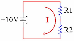
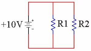
Resistors in Series

The resistors R1 and R2 are in series. The current I flows through both of them.
It is important to understand how to calculate the equivalent resistance of resistors in series.
Notice in the schematic above that the resistors are in line, one after the other. Since resistors work by reducing the current that flows in a circuit, it follows that two resistors reduce the current flowing in the circuit even more. Think of light filters stacked up in a row. The first filter cuts the light by a certain percentage. That reduced light hits the second filter, which reduces the total light by an additional percentage.

Likewise, when current goes through two resistors in series, the total current is reduced because the total resistance has gone up. Equivalent Resistance It turns out that when two resistors are hooked up in series, they present a combined resistance that is equal to their two values added together. When you see two resistors in series, you can add the values together and replace them with a single resistor. The new resistors value is the sum of the previous two resistors. ÃÂ
Original Circuit New Circuit

Resistance Total = Resistor 1 + Resistor 2
This is handy if we need a value of resistance that we do not happen to have on hand at the time. Let's say we need 100 ohms of resistance, but can not find a 100 ohm resistor. We can instead use an 80 ohm resistor and a 20 ohm resistor in series since 80 + 20 = 100.
Circuit Reduction of Resistors
When analyzing circuits it is usually easier to reduce the circuit to a simpler circuit in order to make the math easier. The reduced circuit is mathematically identical to the original circuit. You then use the reduced circuit to answer any questions you have about the original circuit. When you encounter two resistors in series, you can reduce them to one resistor by adding their values together and replacing them with a new resistor that has the value you obtained. ÃÂ
Original Circuit New Circuit


Resistance Total = 100 In the left schematic above we have two resistors in series. In the right picture we have reduced them to a single, equivalent resistor. Now we can use Ohms Law to figure out how much current is flowing through both circuits, since they are mathematically identical. Let's start with Ohms Law in its standard form.

A more useful form for this problem is when it is already solved for I (current).

We know that V (volts) is 10, and R (resistance) is 100. Plugging these numbers in to Ohms Law, we get:
I = V / R I = 10 / 100 I = 0.10 Amps of Current
Now that we know that 0.10 Amps of current are flowing through the circuit, we can go back to our original circuit and label I (current) with the new value.

By using circuit reduction of resistors we have made the math of solving this circuit much easier. Voltage Drop As current flows through a resistor it creates a voltage drop. This means that the voltage drops from a high number to a lower number. You can calculate the voltage drop across each resistor by using Ohms Law. We'll use the same example as before.
We will use the basic form of Ohms Law to determine the voltage dropped by each resistor.
You can apply this law to each resistor in the series. Use I = 0.10 for both resistors because the same current is flowing through them both. We will use Vr1 to mean the voltage dropped by R1 (the 80 ohm resistor) and Vr2 to refer to the voltage dropped by R2 (the 20 ohm resistor). You will notice the green A, B and C added for reference in the next paragraph.

We have applied Ohms Law to both R1 and R2 to determine how much voltage is dropped by each. From the math, R1 drops 8.0 volts while R2 drops 2.0 volts.
Now think about point A (in green) for a second. The voltage at that point is +10V because it is connected directly to the +10 Volt battery. Resistor R1 is going to drop 8.0 volts as current I flows through it. That means that point B (in green) is 10 - 8, or 2 volts.
We have 2 volts at point B. Resistor R2 is going to drop 2.0 volts as current I flows through it, leaving us with 2 - 2 = 0 volts at point C. This makes sense, too, because point C is the negative terminal of the battery, which we tend to always associate with 0 volts.
It turns out that the voltage dropped by R1 + R2 will always add up to the value of the battery.
Voltage Divider
This circuit is so useful in electronics that it has its own name, a Voltage Divider. A voltage divider is used to divide a large voltage into smaller voltages. When designing a voltage divider, you do not have to do all of the math that we did above, there is a short cut. First we have to name a couple of points appropriately.
- The battery is called Vin (for Input Voltage)
- The voltage at point B is called Vout (for Output Voltage)
The point of a voltage divider is to create a new Vout based on a given Vin. Here is the generic circuit.

We can generalize the solution for the value of Vout using the following equation.

Let's break this down. Vout is equal to Vin times everything in the parenthesis. The value in the parenthesis is the ratio of the bottom resistor to the sum of the two resistors. Using the example above:

We start by plugging in the values we know.

Now add 80 and 20 together to get 100.

20 divided by 100 is .2.

Finally, multiply 10 times .2 to get the answer, 2 volts.
The answer of 2 Volts is exactly the same as the answer we got by using Ohms Law above. In fact, the Voltage Divider equation is created by using algegra to rearrange the equations on the previous page into one big equation. The answers will always be the same. You can use which ever method you like better.
Resistors in Series
Resistors in series will show up many times in electronics. When resistors are in series, the current through both resistors is the same. Each resistor will drop voltage as the current passes through it. We use this voltage drop to create new voltages with a circuit known as a voltage divider. With these techniques you are able to create any voltage that you need in your project, as long as Vout is less than Vin.