When we talk about electronics it is sometimes easier to use a picture to describe what we are talking about.
Those pictures are called a schematic. A schematic is a picture representation of what we are talking about in electronics. They may look hard to read at first, but in time you'll find that they are usually easy to read. The hard part tends to be finding the parts that are represented in the drawing. Lets look at a simple schematic, and learn to read what it says.
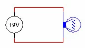
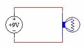
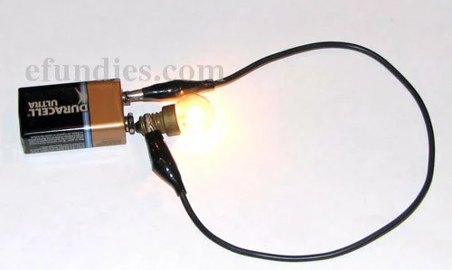
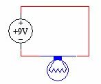
Above is a schematic of a battery hooked up to a light bulb. Here is what it looks like in real life.
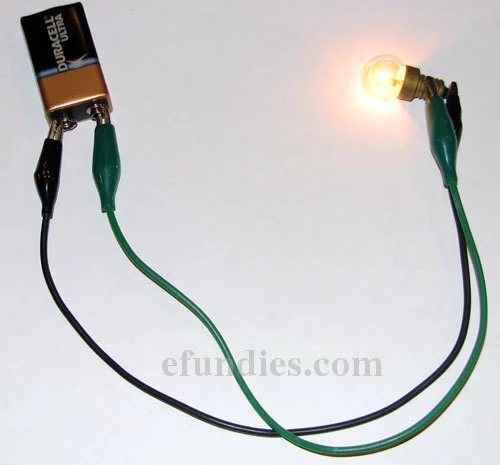
We have used a standard Duracell 9V battery and a light bulb. Notice that the light bulb is on. Now we are going to hook up the light bulb the opposite way.
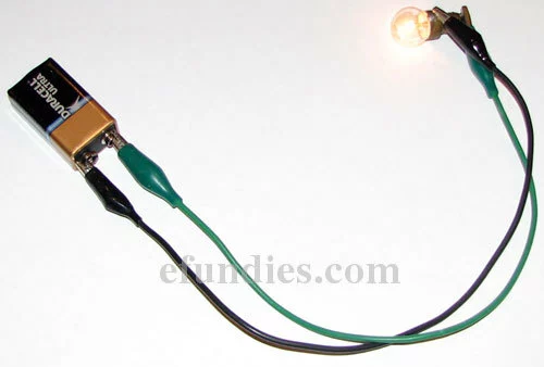
Notice that in the first picture the green wire went to the top area of the light bulb, and in the second picture the black wire went to the top area of the bulb. That is the only change. See that the light is still on? That is because light bulbs do not care about which side of the battery they are connected to. Some devices do care. When that is the case, the schematic will indicate which way to hook the device up. We'll talk more about that later. Now lets talk about the different ways that this can be drawn. All of the schematics below describe the exact same thing. There is absolutely no difference in any of these schematics.
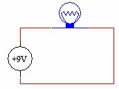
Example 1: light bulb on top.
Example 2: light bulb on side.
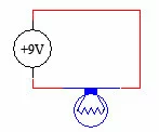
Example 3: light bulb on bottom.
In all three schematics above, the following information has been conveyed
- Connect one side of the battery to one side of the light bulb with a wire.
- Connect the other side of the battery to the other side of the light bulb with a wire.
See how all three schematics all convey the exact same meaning? Now lets look at a few different ways that we can hook a light bulb up to a battery. Keep in mind that all 3 of the pictures below are the same way of realizing the previous schematic, and all 3 are valid and correct.
Example 1, light bulb with 2 wires.
Example 2, light bulb touching top of battery with a wire connecting to the bottom of the battery.
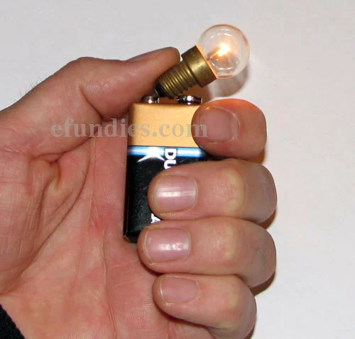
Example 3, light bulb pressed against the battery without any wires.
In all of these cases the light bulb is lit up. All 3 examples above are valid representations of what the schematic is telling you to do. It doesn't matter if you use wires or make parts touch by simply pressing one part against another. The point is that you are making electrical contact between all parts that need to be connected. So when it gets down to it, that's all that a schematic is really telling you. It is telling you to make electrical contact between parts. It doesn't tell you how to make that contact, just that you need to make it. It is up to you to decide the best way to make that contact depending on your project. Now, lets go back to the part we skipped before about which direction things get hooked up. For a light bulb it doesn't matter which way it is hooked up, it will work both ways so in this example we do not have to worry about it. In most circuits you do have to think about the way that certain parts go. This is the concept of polarity. The terminals or legs of a device are frequently marked with a (+) and sometimes a (-). The (+) side is called the positive leg, or is said to have positive polarity, while the (-) side is called the negative leg, and has negative polarity. You can just say positive and negative if you like, most people do. Lets take a close look at the 9V battery we've been using and see if we can figure out which leg is positive.
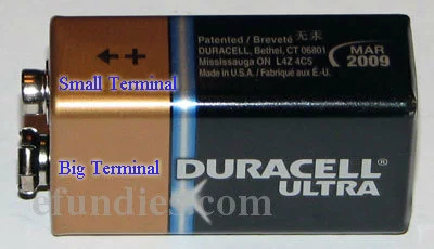
See how the small terminal has a + sign pointing to it? That's the positive leg. To represent this particular leg we put a + sign in the schematic on the appropriate side of the battery. Take a look at how this looks. We'll reshow all 3 previous schematics with the polarity added.
Notice that in these pictures we have properly designated the positive terminal of the battery. It still doesn't matter how we hook it up because we are just hooking it up to a light bulb, which doesn't care about polarity. V+ and GND This is very important. In many circuits the most positive point, or the positive terminal of the battery in this case, is called V+. This stands for Voltage Plus, or Voltage Positive. You can pronounce it "vee plus". Likewise, the most negative point, or the negative terminal of the battery in this case, is called Ground, abbreviated GND. Many circuits will label V+ as Vcc ("vee cee cee"). For the most part, these two terms are interchangeable. Lets look at the symbols for V+ and GND.

Above is the symbol for V+ when we are talking about a 9V source. The number may change, but we can still call it V+.

Above is the symbol for GND.
This is done to make schematics cleaner and easier to read. Most schematics that you will find will have these abbreviations in them. To make schematics even neater, many people leave out the battery all together and simply draw lines connecting to Vcc and GND. This can really clean up a big schematic where lots of parts connect to Vcc and GND. Lets take a look at the same schematic that we've been working with drawn with Vcc and GND.
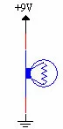
The same circuit drawn with V+ and Gnd.
Notice that this represents the exact same thing. One side of the light bulb is connected to the positive terminal of the battery, and the other side is connected to the negative side of the battery. The light bulb will be on. So far we have been using a circle with +9V in it to represent a battery. This is actually the symbol for a voltage source. A battery makes a great voltage source, so it is valid to use a battery when you see a voltage source drawn in the schematic. Sometimes a schematic will be drawn with a different symbol to specifically represent the battery. That symbol looks like this.
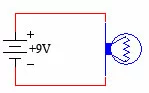
The same circuit drawn with a battery instead of a voltage source.
This is the official symbol for a battery in a schematic. You will not see it as often as V+ and GND. Notice that it still has +9V next to it. This is designating that a 9V battery is required. Other common voltages are +5V and +12V. When you see those voltages, you need to find an appropriate voltage source, such as a different sized battery. Take one last chance to look back at all of the schematics and all of the real life implementations in this guide, and keep in mind that all of them describe the exact same thing. They are all correct and valid representations of the exact same electrical connections. If you have made it this far in the guide, then you are ready to read our next guide, Common Schematic Symbols, where we introduce you to the most common symbols that you will want to be able to recognize.