Signals and Systems is a common term that is used to refer to system design. It is not specific to electronics. You may be reading these guides to learn how to design your own systems, and you may be reading these guides simply to learn how electronics work. In either case, understanding the concepts of signals and systems is an important step in moving on in electronics.
This guide is written as a high-level concept, so please do not try to memorize the exact words that you read. Try to not get focused on a single paragraph in this guide, but instead try to absorb it as a whole. There is no strict definition for what a system or a signal is.
A Simple Example Of A System


The tin cans and string are a system, and your voice traveling on the string is a signal. Collectively, the whole contraption is a system. However, you can break the system down into its individual parts, which are the cans and the string. The tin can in itself is also a system: you can hold it to your ear and tap on the bottom and hear sound out of it. The tin can is converting tapping motion into sound.

The concept of signals and systems is that you can break large, complex systems down into much smaller, easier to understand systems.
Systems In electronics it is frequently easier to break projects down into their smallest components. By doing this we can design the components independent of each other. Then after each component has been fully designed and tested, we can connect all the components to each other. If every individual component functions, then the final resulting system should function as well.

Microphone Amplifier
A good example of this is a microphone amplifier. The end goal is to make an amplifier that has a microphone hooked up to one side, and a loudspeaker connected to the other. Four systems are needed.
- A microphone
- A system that knows how to amplify the microphone's signal to a known level.
- A system that knows how to amplify from the known level to the high level that speakers require.
- A set of speakers
A microphone to speaker amplifier might look like this.

Notice that there is only one line connecting each small system within the large system. That line is the signal traveling from one block to the next.
Signals
In electronics it is usually easier to talk about voltages like they are signals flowing through systems.
It is generally just assumed that GND is 0 volts. So when a signal or voltage of 5 volts is needed, this is in reference to GND. Signals sometimes carry information, such as voice or data. When this is the case, the signal voltage usually goes up and down very rapidly to represent the information.
In the microphone amplifier example earlier, the line connecting each block of the system is carrying voice from the microphone to the speakers. Really what is happening is the voltage on that wire is going up and down very rapidly in response to the voice.
Schematic Simplicity
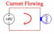
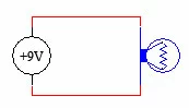
If you have been following these guides from the beginning, then you are pretty familiar with schematics that have a battery, and a large loop for current to flow in a circle in. This is a perfectly valid way of representing a circuit.
However, many designers prefer a slightly abbreviated version. Let's take a look at an example.
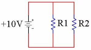
Circuit with Loops

Circuit with GND and V+

These circuits are equivalent.
The reason many people prefer the layout on the right is it makes the circuit look less complicated. Each system that has a signal going through it is going to need +V and GND, so the special symbols for +V and GND above are used instead of drawing long lines all over the schematic.
Transistor Example
In our Transistor Guide we modulated the speed of a motor with our voice using a microphone (really a speaker), an FET and a motor. Let's look at that example again, only this time we are going to draw it with +V and GND symbols.
Circle Method

Signal Method

These circuits are electrically identical.
On the left is what we will call the "circle method" of drawing this circuit. Where are the systems? Where are the signals? It is less clear because the battery and GND connections get in the way. However, using the "signal method" on the right the two systems are more isolated. With the systems isolated it is much more clear which wire carries the signal from the microphone to the FET. See below.

In this example, System #1 is the Microphone and its connection to GND. System #2 is the motor, FET and their respective power connections.
After circling the two systems, the signal wire connecting the two is the only thing that is left. We made up the names System #1 and System #2. You can call them whatever you want.
A Way to Think of Signals and Systems
In general, signals travel in circuits horizontally and from left to right like we read. However, this is not a hard and fast rule; there are plenty of times where signals travel from right to left or vertically.
Also, note that there is a second, unused signal in the circuit above. Can you spot it?
It's the wire between the FET's Drain and the bottom of the motor. The voltage on that wire is not 0V because it is not connected to GND, and it is not +10V because it is not connected to +10V. It is actually a signal voltage, somewhere between 0V and +10V that will change as the microphone picks up sound. If this is confusing, don't fret it, it will make more sense later.
Lastly, the +V in a circuit is frequently referred to as Vcc. This is a bit of a throwback to BJT transistors when the + rail was connected to the collector leg of the transistor. Collector is the 'c' in Vcc. So when you see Vcc, just think +V and you'll be fine.
About Signals and Systems
We feel that this is a necessary guide in our Intermediate Electronics Fundamentals series of guides because many schematics can be analyzed in terms of signals and systems.
In addition, it is necessary to learn to read schematics that have +V or Vcc and GND in them since many circuits shared on the web are drawn this way.