Make sure that you have the STK500 user guide on hand. It describes in detail all of the steps that we will describe here.
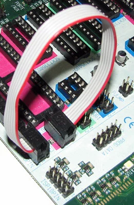
You can find a copy of it on the Atmel website, direct link ishere. Since the ATMega32 gets socketed in A3 on the STK500, an A3 is a pink colored socket, this means that you must connect a 6 pin jumper from ISP6PIN to SPROG3.
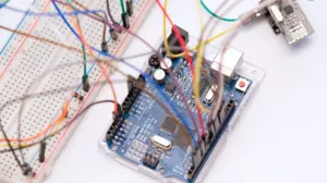
Serial Cable
You also need a serial connection to the serial port on the STK500 labeled as RS232 CTRL. If you computer does not have a serial port, then you can use a USB to serial converter. We use Trendnet TU-S9 for this purpose and have never had a problem with them.
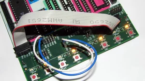
Ready To Program
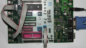
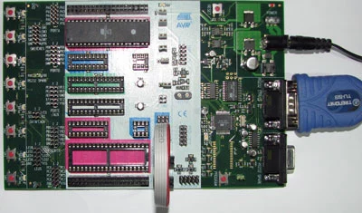
Make sure that you have your ATmega32 socketed in the correct socket, the serial cable connected, and the ISP jumper installed. Apply power to the STK500 and the power light should turn red. When everything is setup correctly, this is what your STK500 should look like.
AVRStudio Setup
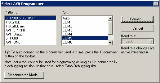
Fire up AVRStudio and compile your project. If you are following these guides then your project should already be compiled. Click the black CON button on the AVRStudio button bar, and you should see the Select AVR Programmer dialog box. Pick STK500 and the correct serial port like this:
After you click Connect you should see a new dialog box called STK500 in ISP mode with ATmega32.
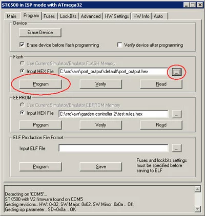
Inside the frame called Flash click the button with 3 dots on it to browse for the .hex file created when you compiled. It should be in the default subdirectory of where your project is located. Then click the Program button to flash the .hex file into the AVR's flash memory.
If you do not have some sample code to flash into your chip, check out our AVR Port Output Using C guide.
After the code is completed flashing into the AVR, the STK500 will reset your chip and it should start executing the code that you downloaded.
If you just downloaded the code from the previous guide, then the LEDs should light up in an alternating pattern.
If The LEDs Do Not Turn On
The most likely cause of the LEDs not turning on is that the cable between PORTA and LEDS is not connected correctly.
If that is not the case, then the next most likely cause is that the AVR chip is not getting the correct clock. There are 3 ways to clock a chip in the STK500:
- Use the internal clock of the chip you are programming. This is the default behavior of a new AVR from the factory.
- Use the synthesized clock of the STK500
- Use a crystal inserted into the STK500 crystal socket
Bitwise Operations
It's time to move on to bitwise operations. Our next guide shows you how to manipulate bits in the AVR, and introduces some very handy macros. Or head back to our index of AVR Guides here.