 |
HB3x2 Dual 3 Amp H-Bridge for Robotics
|  |
HB3x2 Assembly Guide
The HB3x2 has been designed to be easy to build and start using. We hope that this assembly guide helps you get your HB3x2 kit together in a short amount of time. If you have any questions while assembling your HB3x2 don't hesitate to email us. Contact info is at the bottom of this page.
If you are new to surface mount soldering then you may want to read the excellent tutorials over at SparkFun. Sparkfun Tutorials on SMD Soldering
Necessary Tools
You will need a few tools to assemble your HB3x2. Most importantly you should have the following:
- Needle nose tweezers
- Fine tipped soldering iron
- Flux
- Solder tip cleaner
- Magnifying glass
Step 1 - Identify All Components
Open up your kit and layout all components to make sure that your kit has everything listed here.
| Quantity |
Desc |
Picture |
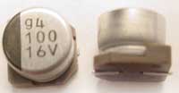
| 2 |
100uF electrolytic caps, marked 100 16v |
 |
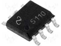
| 2 |
LM5110 MOSFET driver |
 |
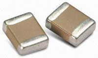
| 3 |
.1uF ceramic caps, brown, no numbers |
 |
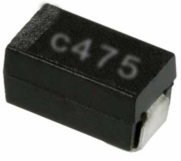
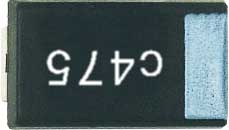
| 1 |
4.7uF tantalum cap, marked c475 |
 |
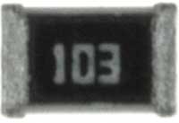
| 4 |
10k resistor, marked 103 |
 |
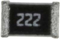
| 4 |
2.2k resistor, marked 222 |
 |
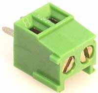
| 1 |
terminal block (may be black instead of green) |
 |
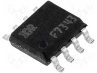
| 4 |
IRF7343 output FETS |
 |
| 1 |
male header, 10 pin |
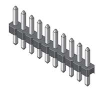 |
| 1 |
Printed circuit board, or PCB |
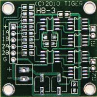 |
Step 2 - Solder The Smallest Components
Referring to the Board Layout solder down the 2.2k resistors, the 10k resistors, and the 0.1uF capacitors. None of these components have polarity concerns so you can put them on the board with either side on either pad.
Step 3 - Solder the Tantalum Capacitor
After the small resistors and capacitors are soldered in place you can solder the 4.7uF capacitor.
The 4.7uF capacitor is polarized and must be soldered in the correct orientation. The white band connects to the positive rail and should be to the right if the PCB is oriented with the text right side up. The text on the capacitor will most likely be upside down when the capacitor is in the right orientation.
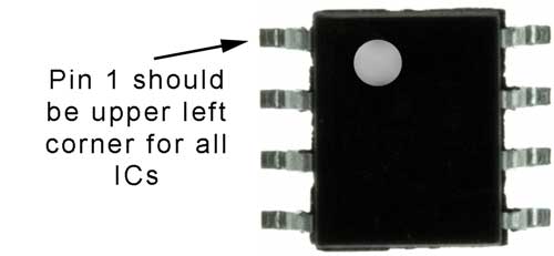
Step 4 - Solder the Integrated Circuits
Now it's time to solder down the 2 LM5110 integrated circuits and the 4 IRF7343 integrated circuits.
The integrated circuits also must be oriented correctly. All 6 of the IC's should have a small dot in the plastic designating pin 1, and it should be in the upper left corner of the chip as it is laid out on the board. See the following picture:
Step 5 - Solder the Electrolytic Capacitors
The last surface mount component to be soldered should be the large electrolytic capacitors. They have a non square footprint that is matched by a white patern silkscreened onto the PCB. Make sure that the footprint of the electrolytic capacitors aligns with the white footprint.
NOTE: The terminal block power connector is very close to the capacitors. If you are going to error in capacitor placement, error in the direction away from the terminal block.
Step 6 - Solder the Through Hole Components
Once all of the surface mount components are mounted you can tackle the through hole parts. Break the 10 pin male header into a 6 pin section and 2 2 pin sections. Solder them in place. Then solder in the terminal block last. Make sure that all of the through hole components get lots of solder because they will take a little bit of abuse as you connect and disconnect from them.
That's it, you're done! You might want to check out our Testing and Troubleshooting Guide to make sure that your board is assembled correctly. Have fun.
If you have any questions email me here: jason (at) efundies.com
* Free shipping offer valid only in the United States.
|