 |
HB3x2 Dual 3 Amp H-Bridge for Robotics
|  |
HB3x2 Testing and Troubleshooting Guide
How it Works
The way the HB3x2 is designed your motor will be stopped any time both input pins for that motor, 1A and 1B for motor 1, are at the same level. If both input pins are high then the motor is stopped. If both input pins are low then the motor is stopped. Any time the input pins are opposite, one high and one low, the motor will spin. The direction it spins is based on which input pin is high and which input pin is low and how the motor is wired. Most of the time you figure out spin direction with some experimentation.
Power Only Test
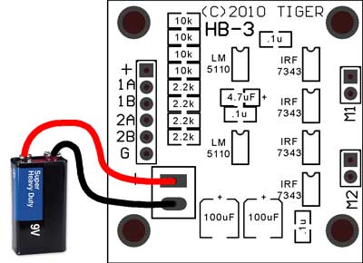
Start out with nothing connected to your HB3x2.
Connect just the incoming power to the large terminal block. This is best done with a low current device such as a couple of AA batteries, a 9 volt, or a current limited bench power supply. With just the power connected carefully place a finger on the integrated circuits and feel for warmth. They should not get warm. If they start to get warm disconnect power immediately and look for a solder short on the board. With nothing connected other than power the IC's should not get warm.
Low Current Motor Test
Disconnect power. Now track down a small, low current motor to test with. Something like a pager motor or small hobby motor. Connect the motor to one of the motor termals so that one lead of the motor connects to Motor 1A and the other lead to Motor 1B. Reconnect your current limited power source. The motor SHOULD NOT SPIN at this point in time. Carefully feel the IC's and make sure that they are not getting warm. If they are then disconnect power and look for shorts again.
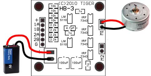
To make the motor spin take a small jumper wire and connect it between GND and 1A on the 6 pin header. The motor should spin one direction. Now connect the wire between GND and 1B on the 6 pin header. The motor should spin the other direction. Verify that the IC's do not get hot while the motor is spinning.
Pulling an input pin low will spin the motor because the input pins are held high by the 10k pull up resistors. With nothing connected to the input pins the H-Bridge both input pins for each motor are held high and the motor is stopped. As soon as you pull one or the other input pins low current is allowed to flow through the output FETs and through the motor causing it to spin. The current direction is controlled by which input pin you pull low so alternatly pulling 1A and 1B low should alternatly cause the motor to spin forward and backwards.
PWM Speed Test
Now we can test controlling the speed of the motor. You will need a source of a PWM signal. This is simply a square wave with adjustable duty cycle. Duty cycle is the ratio of high time to low time in a square wave. A bench function generator is the easiest source of this kind of signal, but it can also be generated out the pin of any microprocessor that you are comfortable with. The frequency is not critical. Anything between a few hundred hertz and 1 megahertz should work just fine (100hz - 1Mhz). If you do not know how to generate a wave like this then check out the programming examples on the right of this page.
Set your PWM to roughly 50% duty cycle.
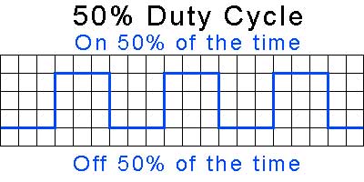
Leave pin 1B pulled high by the internal pull up resistor and connect your PWM square wave to pin 1A. The motor should start to spin at roughly half speed. Since pin 1B is high, when your square wave is high the motor is stopped and when the square wave is low the motor is spining in a given direction. Now try pulling pin 1B low. The motor should spin the other direction but still be roughly 50% speed.
Try adjusting your PWM signal so that it is no longer 50% duty cycle. Try setting it to something around 75% duty cylce. That means on 75% of the time, off 25% of the time.
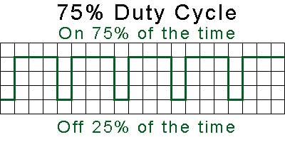
Now with pin 1B high your motor should spin at roughly 25% speed in one direction, and with pin 1B low your motor should spin at roughly 75% speed the other direction. This is because the PWM signal is high 75% of the time. With pin 1B high the motor is in brake 75% of the time (high on 1B plus high signal = brake), or in motion 25% of the time (high on 1B plus low signal = go).
When you pull pin 1B low the motor now goes the other direction but it's in motion for 75% of the time (pin 1B low and pin 1A high 75% of the time). This inverse relationship of duty cycle and motor direction is usually dealt with in software and it turns out to be very easy to handle.
If you have any questions email me here: jason (at) efundies.com
* Free shipping offer valid only in the United States.
|