Insteon J5 Header Pinout
Oh happy day...
If you are like me, you've been waiting to dive into wiring up some devices to your Insteon modules. Well we're one step closer today. The J5 header pinout has been documented.
The names of the pins are as the correspond to the PIC documentation. You can get the documentation here.
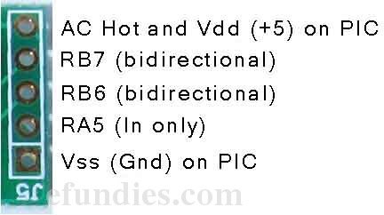
It seems that we have access to pins RB6 and RB7, as well as +5V and Gnd.
In case you don't know where the J5 header is, this picture will help get you oriented.
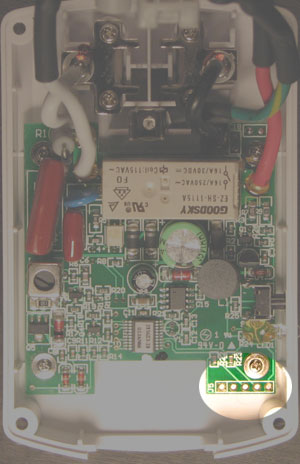
See the square connector? That one is on the left in the picture above. The square connector is Vss, or Gnd.
WARNING: The pin below marked +5V connects to AC Hot and is LETHAL. It is marked +5volts because it appears to connect to the PICs +5v pins. Be carefull here.
Thanks to BLH on the forum for pointing out the most likely method that the On/Off modules get their power for the PIC CPU, based on a writeup from microchip.com. You can find the writeup here.
Thanks to TAD on the forum for pointing out that the previously unknown pin on J5 goes to pin 4 on the PIC chip. According to tad: "I haven't got any of the Insteon kit but as someone who's used a lot of PICs in a professional capacity I'd say it's a fair bet the unknown pin on J5 goes to PIC pin 4, MCLR. With RB7, RB6, MCLR, GND and VDD you have an ICSP (In Circuit Serial Programming) connector. And since the part is a flash (16F) device it can be reprogrammed."
Ra5, Rb6 and Rb7 are described as this in the PIC documentation:
- RA5/MCLR/VPP Input port
Master clear. When configured as MCLR, this pin is an active low Reset to the device. Voltage on MCLR/VPP must not exceed VDD during normal device operation.
- RB6/T1OSO/T1CKI/ RB6 TTL CMOS Bidirectional I/O port.
Interrupt-on-pin change.
Can be PGC software programmed for internal weak pull-up.
T1OSO — XTAL Timer1 Oscillator Output
T1CKI ST — Timer1 Clock Input
- PGC ST — ICSP Programming Clock
RB7/T1OSI/PGD RB7 TTL CMOS Bidirectional I/O port.
Interrupt-on-pin change.
Can be software programmed for internal weak pull-up.
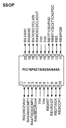
Here is a screenshot of the PIC 16F648A pinout. You can see that RB6 and RB7 connect to pins 13 and 14, and RA5 connects to pin 4.
That's all we know so far. If you have anything to add, please head over to the forum.
|