The AVR series of microcontrollers reference their I/O ports as PORTA, PORTB, PORTC, PORTD and so on.
Each port has up to 8 bits, each of which can be configured as either an input or an output.
How To Configure AVR Port Pins
For instance, you can configure the first 4 bits of PORTA to be used as inputs, and the upper 4 bits of PORTA to be used as outputs. Data Direction Registers In the AVR series of microcontrollers, before you can use a port for input or output, you should make sure that the port is configured as either an input or as an output. This is done with the Data Direction Registers, or DDR. There is a DDR for each of the ports on your chip, such as: DDRA, DDRB, DDRC, DDRD and so on.
Each DDRx register is 8 bits wide. By writing a 1 to any bit of the DDRx register, you are configuring the corresponding pin on PORTx to be an output.
DDRx: 1 = PIN CONFIGURED AS OUTPUT
Likewise, if you write a 0 to a pin in the DDRx register, you are telling that pin to be configured as an input. We cover port input in our AVR Port Input guide.
To set up all bits of PORTA as output, you need to write all 1's to DDRA. The following 2 commands are identical and will set up all PORTA pins as outputs.
DDRA = 0xFF;
DDRA = 255;
Both lines write the binary pattern 11111111 to DDRA, so each pin of PORTA will be in output mode.
You can use either line in your program. Port Output To actually send data out the port, you simply assign the value that you want sent out the port to the predefined location PORTx (replace x with the correct port). So to send data out PORTA, after you have initialized it for all outputs, the following lines will work:
PORTA = 0xAA;
PORTA = 170;
Both lines write the binary pattern 10101010 to PORTA. If you have LED's connected to the port pins associated with PORTA, you would see every other LED come on.
When you write a 1 to a port output, you are telling that port pin to go HIGH. Likewise, when you write a 0 to a port output, you are telling that port pin to go LOW.
PORTx: 1 = OUTPUT PIN DRIVEN HIGH
Sample Code
Here is a complete example of the above concepts, ready to be pasted in to your AVRStudio and compiled.
// ********************************************************************************
// Includes
// ********************************************************************************
#include <avr/io.h>
#include <stdbool.h>
// ********************************************************************************
// Main
// ********************************************************************************
int main(void)
{
// configure PORTA as output
DDRA = 0xFF;
// main loop
while (true)
{
// turn on every other bit on PORTA, pattern 10101010
ÃÂ ÃÂ ÃÂ ÃÂ ÃÂ ÃÂ ÃÂ ÃÂ PORTA = 0xAA;
}
}You can download the complete source code here.
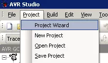
Go Ahead, Compile It
You should be able to copy and paste this code directly into your AVRStudio and hit the Build Active Configuration button (it looks like a white bin with 2 blue down arrows, or press F7). For me, this code compiles to 160 bytes.
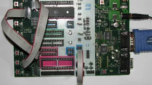
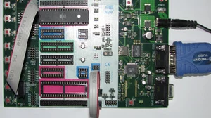
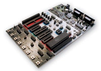
Hook Up The LEDs
We need to physically connected the LEDs to PORTA. Fortunately this is a very easy step. When you got your STK500 it should have come with a few 10 pin jumper cables. You need to connect PORTA to LEDS with one of those cables. Make sure that the red stripe is on the same end on both sides. We always put the red strip on LED0 and PA0 as labeled on the board.

If you've done everything right, then when you turn the board on your code should execute from flash memory, and LED0, LED2, LED4 and LED6 should light up (that's the bit pattern AA that we sent out). Notice that on the STK500 the LED's are wired in reverse logic, so writing a 1 to a port pin turns the LED off.
Writing The Code Into Flash Memory
Now that you have code compiling that actually does something, we need to copy it into your chip so that we can see it run. Check out our next guide to learn how to program your compiled program in to your AVR microcontroller using the STK500. Or head back to our index of AVR Guides here.